
So I found an old Nokia 3310 in trash at work, seems like a waste so I took it home and re-purposed it 🙂
I thought that I can put in to the chassis some of the displays that I use for arduino projects but I found out that the 3310 display can be used with arduino and the implementation is very easy due to the fact that the display has metallic pins.
After connecting the display with arduino I started to wonder what else can be done.
So one thing led to another and thus the Nokia Geiger Counter was born, if you are interested in schematics please click read more.
First of all you will need to connect the pins on the display to any arduino (tested with: Uno, Nano, Pro Mini) the following picture shows the dispaly and information where to connect each individual pin.
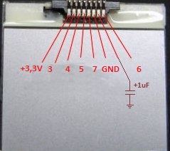
Nokia 3310 disaply pinout
You can not use 5V for the display, so to get at least close to 3,3V you can use 2 diodes in series to lower the generic 5V for arduino.
For the display to be used with arduino you will need to use a dedicated library , there are several of them but I had used this one because it was easy to use and had all the functions that I needed for my project. DOWNLOAD HERE
You can use also other pins if you want, just remember to change also the library defaults.

Digispark (with ATiny85)
Arduino Nano or Pro Mini fits to the phone very nicely. The library does not use much memory and for a simple project you can also use very small and cheap Digispark with ATiny85
If you want to make a geiger counter you will need to get 300-400V for almost any geiger muller tube.
In my particular projet I had used a super small SBM-21 however due to it’s size it is super insensitive to small radiation amounts.
To get the correct voltage about 300V for the SBM-21 I had used a circuit that I know that works and works great in the GC10 (aka Kinoko Geiger counter)
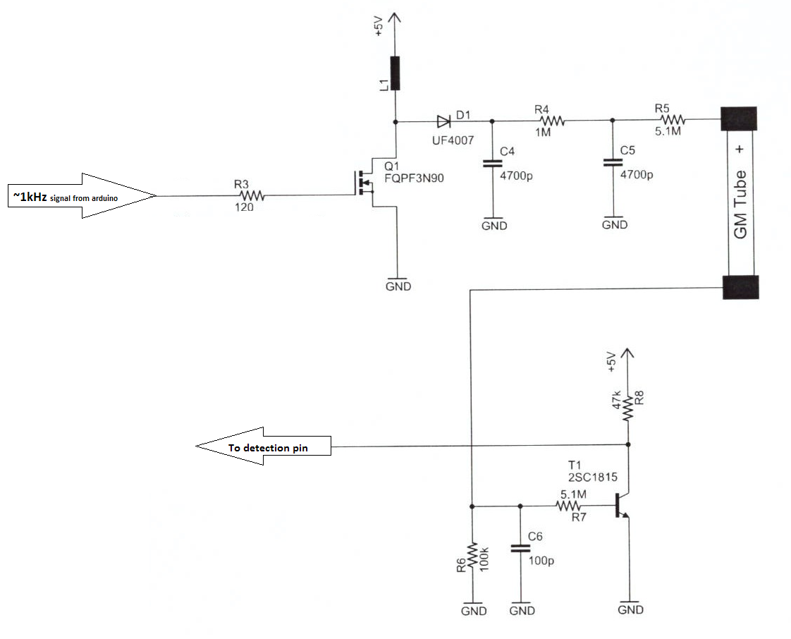
HW power supply + detection circuit
This Generator can be regulated by changing the frequency and pulse width. However I do recommend replacing the main transistor for a cheaper one and one that is more easy to get : IRFBE30 works just as well but it has limit of 800V (instead 900V with the original) or any other that has similar characteristics.
Also feel free to use any “audio range” NPN transistor for the detection part.
Input for this generator is your frequency from arduino, output must be put to any pin that uses interrupts. In my case it was pin “D2”, you don’t want to register of counts in the “loop” procedure because that will be very slow and arduino wont be able to count much CPM.
From all of my tests I reached limit of 68 000 CPM with SBM-20 tube, which makes about 450uSv/h , from what I know for sure the source I have has 158 000 CPM so there is probably some limit for the arduino working together with the display etc… dont know.
But that is sufficient for building a reasonably functional counter.
Here are some snippets from my arduino sketch, I am a bit embarrassed by my poor coding so I wont post the whole thing.
To create the frequency you can use this in your “setup” procedure :
pinMode(10, OUTPUT);
TCCR1A = 0;
ICR1 = 37250; // Here you can set the frequency that delivers the desired voltage
TCCR1A = (1 << WGM11);
TCCR1B = (1 << WGM13) | (1 << WGM12) | (1 << CS10);
DDRB |= _BV(1) | _BV(2);
TCCR1A |= 2 << 6;
TCCR1A |= 2 << 4;
OCR1A = ICR1 * 2 / 10;
OCR1B = ICR1 * 2 / 10;
I had found this code online, and I am not very certain what it does, but I am sure that it uses both ports of the timer (pin 9 and 10 on arduino).
With this setup, the 400V power supply draws only 5mA of current.
To register interrupt you can use the following:
Add this to “setup” procedure :
attachInterrupt(0, counter, RISING);
and add this procedure:
void counter()
{
total++;
}
The total variable will hold the amount of total hits recieved and you can calculate the CPM from it.
And that is all, if you need some help with the arduino sketch you can contact me on my e-mail